Week 10 · Processors and HLS · Lesson 22 of 24
High-level synthesis for FPGAs: C++ to RTL with pragmas
How HLS tools turn C++ into hardware: scheduling, latency and initiation interval, loop pipelining, unrolling, array partitioning, dataflow and AXI interfaces.
What you will learn
- Describe what an HLS tool decides for you: schedule, resources, interfaces and storage
- Write C++ that HLS tools accept, and say which language features they reject
- Calculate the latency of a pipelined loop from its iteration latency, trip count and initiation interval
- Choose pipeline, unroll, array_partition and dataflow pragmas for a loop nest and predict their effect
- Verify an HLS kernel in C simulation against a NumPy reference before synthesis
Before you start
- FIR filters and fixed point (lesson 15)
- Soft processors and AXI4-Lite (lesson 21)
- Basic C++: functions, arrays, loops
After this lesson you can read an HLS kernel and predict the hardware it asks for, compute the latency of a pipelined loop, and pick the pragmas that reach a throughput target. The example is the same 31-tap FIR filter you wrote by hand in lesson 15, now as C++ with pragmas, tested in C simulation against NumPy.
The main reference is Parallel Programming for FPGAs by Kastner, Matai and Neuendorffer, an open book under CC BY 4.0. Page numbers refer to the arXiv version.
What an HLS tool does
High-level synthesis takes a function written in C, C++ or SystemC and produces RTL. You give it the function, a testbench that calls it and checks the results, a target device, a clock period and directives (Kastner, p. 12). The tool then makes the decisions an RTL designer makes by hand. The HLS process includes algorithms for scheduling, allocation and binding (p. 7); the rest of the list follows pp. 11 to 12:
- Scheduling: which clock cycle each operation runs in, and where registers go so that every path meets the clock period.
- Allocation and binding: how many multipliers, adders and memories to build, and which operation uses which unit.
- Control: a state machine that sequences the datapath.
- Interface synthesis: ports and protocols that connect the function to the rest of the system.
- Storage mapping: which arrays become registers, LUT RAM or block RAM.
The output is synthesisable Verilog and VHDL, which then goes through the normal flow of lesson 3 (p. 13).
The C++ that HLS accepts
Hardware has a fixed structure, so code that creates structure at run time cannot be synthesised. Kastner lists the usual restrictions (pp. 12 to 13):
- no dynamic memory allocation (
malloc,free,new,delete); - no recursive function calls;
- limited pointers-to-pointers, function pointers and virtual functions: every call must be known at compile time;
- system calls such as
printfare ignored in synthesis, so they may stay in the testbench; - only part of the standard library, and the interface must be fully defined.
What you get in return is control over bit widths. Instead of int, a tool library offers arbitrary-width types such as ap_int<width> (p. 48). The example below uses <cstdint> types so that it compiles anywhere; in a real flow the 64-bit accumulator could shrink to 37 bits, the worst-case width for 31 products of 32 bits.
Latency and initiation interval
Two numbers describe the speed of a hardware function. Latency is the time from when a task starts to when it finishes. The interval is the time from the start of one task to the start of the next (Kastner, pp. 20 to 21). For a loop the interval between iterations is the initiation interval (II): the number of clock cycles until the next iteration can start (p. 45).
Vivado HLS, the tool Kastner uses, runs loop iterations one after another by default (p. 43). If one iteration takes L cycles, N iterations take about N × L. Loop pipelining starts a new iteration every II cycles while earlier ones are still running, as an instruction pipeline does in a CPU:
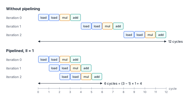
Kastner’s FIR example shows the effect: a multiply-accumulate loop of 11 iterations with a 4-cycle body has a latency of 44 cycles without pipelining and 14 with II = 1 (pp. 43 to 45). For a long loop, throughput is set by II and the iteration latency hardly matters.
Loop and memory pragmas
The pragmas below use the AMD Vitis HLS syntax. Other tools use different spellings for the same ideas.
Pipelining
#pragma HLS pipeline II=1 inside a loop asks for a new iteration every cycle. The II is a target. If the tool cannot reach it, Vitis HLS issues a warning and builds the design with the lowest II it can achieve (UG1399, Pipeline). Data dependencies and memory ports are the usual limits. Kastner’s example: a delay line in a single-port RAM needs a read and a write in the same cycle, which one port cannot do, so II = 1 is impossible (p. 45).
Unrolling
#pragma HLS unroll factor=4 copies the loop body four times and runs a quarter of the iterations. Without a factor the loop unrolls completely, which needs a trip count known at compile time (Kastner, pp. 40 to 42). Unrolling creates parallel operators, but they only help if the data can reach them: an unrolled loop that reads one array is still limited by the ports of the memory that holds it (p. 90).
Array partitioning
A block RAM has two ports (lesson 14). #pragma HLS array_partition splits an array into several smaller memories or into individual registers, which gives more ports at the cost of more memory instances or registers (UG1399, Array_partition). The type option chooses how elements are dealt out:
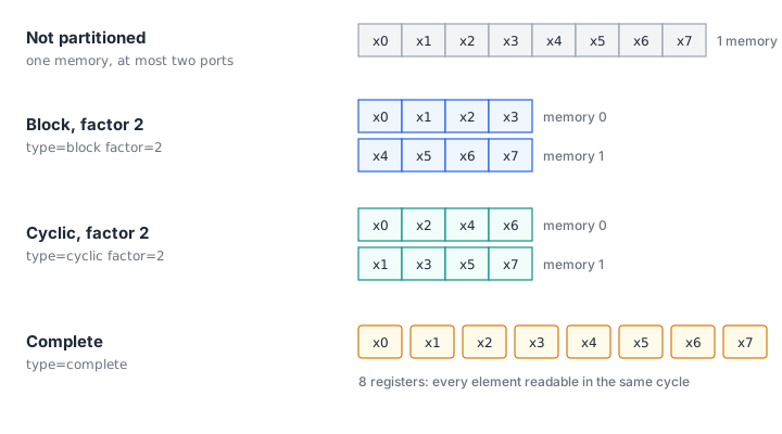
Match the partitioning to the access pattern. A loop unrolled by two that reads x[i] and x[i+1] needs cyclic factor 2, so the even and odd elements sit in different memories (p. 90). A small delay line that the loop shifts entirely every cycle needs complete partitioning (p. 41).
Dataflow
#pragma HLS dataflow lets functions and loops in a region overlap instead of running in sequence: task-level pipelining (UG1399, pragma HLS dataflow). The tool inserts channels between the stages. If a producer writes an array in the order the consumer reads it, the channel can be a FIFO; otherwise it becomes a ping-pong buffer, two copies of the array that the two stages swap after every task (Kastner, p. 115). A common structure is dataflow at the top level and pipelined loops inside each stage.
Interfaces
A kernel has to talk to the rest of the system. The interface pragma maps each argument to a protocol (UG1399, pragma HLS interface):
| Mode | Protocol | Typical use |
|---|---|---|
s_axilite | AXI4-Lite subordinate | scalars, control and status registers |
m_axi | AXI4 manager | arrays in external or shared memory |
axis | AXI4-Stream | sample or pixel streams |
ap_ctrl_hs | block-level start, done, idle, ready signals | control without a bus |
port=return refers to the block-level control of the function itself. Mapping it to s_axilite puts start and status bits into the same register block as the scalar arguments, and the tool produces C driver files for it. That generated block does the job of the hand-written axil_regs.sv from lesson 21. Memory-mapped and streaming interfaces suit different accelerators: one walks through buffers in memory, the other processes data as it flows past (Kastner, p. 19).
Worked example: the FIR filter in HLS C++
The kernel filters a block of len samples. The 31 coefficients are a constant table, identical to those of fir_transposed.sv in lesson 15. The delay line is a static array, so its contents persist between calls and a long signal can be processed in blocks.
void fir_hls(const sample_t in[MAX_LEN], sample_t out[MAX_LEN], int len, int clear) {
#pragma HLS interface mode=m_axi port=in
#pragma HLS interface mode=m_axi port=out
#pragma HLS interface mode=s_axilite port=len
#pragma HLS interface mode=s_axilite port=clear
#pragma HLS interface mode=s_axilite port=return

    static sample_t shift_reg[NTAPS];   // filter state, kept between calls
#pragma HLS array_partition variable=shift_reg type=complete
    // ... if (clear) zero shift_reg; clamp len to MAX_LEN
SAMPLES:
    for (int n = 0; n < len; n++) {
#pragma HLS pipeline II=1
        const sample_t x = in[n];
        acc_t acc = 0;
    TAPS:
        for (int k = NTAPS - 1; k > 0; k--) {
#pragma HLS unroll
            shift_reg[k] = shift_reg[k - 1];          // shift the delay line
            acc += acc_t(shift_reg[k]) * COEF[k];     // multiply-accumulate
        }
        shift_reg[0] = x;
        acc += acc_t(x) * COEF[0];
        out[n] = round_sat(acc);                      // round half up, saturate
    }
}
What the pragmas ask for:
pipeline II=1on SAMPLES: one new sample per clock cycle once the pipeline is full.unrollon TAPS: 31 multiplies per sample, so 31 multipliers working in parallel.array_partition ... completeonshift_reg: 31 registers, so all taps can be read and shifted in one cycle. In block RAM, each iteration would need 30 reads and 31 writes through two ports.m_axion the arrays ands_axiliteonlen,clearand the return: the processor writeslen, sets start, and the kernel fetches and stores samples in memory itself.
round_sat adds 2^14, shifts right by 15 and saturates to 16 bits, the same arithmetic as the RTL. The labels SAMPLES and TAPS name the loops, as in Kastner’s examples (p. 40).
fir_hls.cpp
Download fir_hls.hpp
C simulation first
An HLS flow starts with C simulation: compile the kernel and its testbench as ordinary software. Here that is clang++ with -std=c++17 -Wall -Wextra -Werror, plus -Wno-unknown-pragmas and -Wno-unused-label, because clang does not know the HLS pragmas and nothing jumps to the loop labels.
tb_fir_hls.cpp checks the impulse response against the coefficient table, sends 5000 pseudo-random samples in blocks of 1, 3, 1024, 17 and 600 to prove that the state carries across calls, confirms that clear resets it, and checks saturation: the DC gain is 32770/32768, so a full-scale DC input must clip to 32767. test_fir_hls.py then compares the kernel with fir_ref.py, a NumPy model that designs the coefficients with scipy.signal.firwin, quantises them and filters with exact integer arithmetic. 8000 random samples and a 1 kHz plus 15 kHz test signal match bit for bit. The 1 kHz tone passes with its amplitude within 0.4 %, and the 15 kHz tone, in the stopband, comes out at about 0.1 % of its input amplitude.
C simulation proves the algorithm, not the hardware. After synthesis the same testbench should drive the generated RTL; Vivado HLS, for example, produces RTL simulations based on the design testbench (Kastner, p. 13). Run that step as well, because it exercises the interfaces and the schedule that C simulation never sees.
Downloadtb_fir_hls.cpp
Download fir_ref.py
Download test_fir_hls.py
HLS versus the hand-written RTL
Both versions compute the same numbers, but you control different things. In fir_transposed.sv you chose the transposed structure, so each product feeds a short adder chain that maps onto DSP slices, and you fixed the latency at four cycles. In HLS you wrote a direct-form loop and asked for a throughput; the tool picks the adder structure and the number of pipeline stages from the clock period. To change the trade-off by hand you rewrite RTL. In HLS you change a pragma: pipeline II=4 on SAMPLES accepts one sample every four cycles, so each multiplier could serve up to four taps. Read the tool’s report to see what it actually built.
Tools
- AMD Vitis HLS compiles C and C++ functions to RTL with the interface modes above. Its user guide, UG1399, documents every pragma.
- Altera: the user guide of the Intel HLS Compiler states that the product is discontinued and points to the FPGA support package for the oneAPI DPC++/C++ compiler. Intel’s oneAPI page in turn marks that package deprecated and unavailable from compiler release 2025.1, saying Altera will provide FPGA support through its own tools. Check Altera’s site for the current state before you plan an HLS flow on Agilex.
- Microchip SmartHLS comes from LegUp. Microchip bought LegUp Computing, a company commercialising University of Toronto research, in October 2020, and added the SmartHLS flow to its PolarFire tools in 2021.
- Bambu, from Politecnico di Milano, is an open-source HLS framework under the Apache 2.0 licence with LLVM exceptions. It accepts C and C++ and compiler intermediate representations from Clang/LLVM and GCC.
Pipeline numbers for the FIR kernel
Assume the pipelined SAMPLES loop has an iteration latency of 9 cycles at 100 MHz (an example value; the real figure comes from the tool’s report).
- How long does a call with
len = 1024take at II = 1 and at II = 2, ignoring the AXI transfers? What sample rate can each sustain? - Someone deletes the
array_partitionpragma and the tool putsshift_regin a dual-port block RAM. What is the lowest II possible?
Show solution
- II = 1: (1024 - 1) × 1 + 9 = 1032 cycles = 10.32 µs, and the loop accepts 100 million samples per second. II = 2: (1024 - 1) × 2 + 9 = 2055 cycles = 20.55 µs, and 50 million samples per second.
- Each iteration reads
shift_reg[0..29]and writesshift_reg[0..30]: 30 reads and 31 writes. Two ports allow two accesses per cycle, so the iteration needs at least 61 / 2, rounded up to 31 cycles, and II ≥ 31. The rate drops from 100 to about 3.2 million samples per second, which is why the delay line must be in registers.
Summary
- An HLS tool schedules operations into clock cycles, allocates and binds operators, builds control and interfaces, and maps arrays to storage. You set the targets with pragmas.
- Synthesisable C++ has no dynamic memory, no recursion and calls known at compile time. Arbitrary-width types such as
ap_int<W>control bit widths. - A pipelined loop takes about (N - 1) × II + L cycles; for long loops, II sets the throughput.
- Unrolling creates parallel operators, partitioning gives them memory ports, and dataflow overlaps whole functions. The three only pay off together.
- Verify in C simulation against a bit-exact reference before synthesis, and judge the result by the tool’s reports, not by the source.
Check your understanding
Pick an answer for each question, then check. Answers stay hidden until you submit.
Further reading
- Book
- Documentation
- Paper
- Tool
- Article
Found a mistake or something unclear?Report a correction.
Follow this course
Get an email when new lessons and projects are added to this course.