Week 10 · Processors and HLS · Lesson 21 of 24
Soft processors, RISC-V and AXI4-Lite on FPGAs
Why FPGA designs include a CPU, how RISC-V names its ISA variants, and how to build an AXI4-Lite register file that lets C code control a hardware block.
What you will learn
- Explain when a design needs a processor next to its hardware pipelines, and choose between a hard and a soft core
- Decode RISC-V ISA names such as RV32I, RV32IMC and RV64GC
- Apply the AXI4-Lite VALID/READY rules, including independent write address and data channels
- Design and verify an AXI4-Lite register file that connects software to a hardware block
- Write a C driver for memory-mapped registers and test it on the host with a mocked register array
Before you start
- Finite state machines (lesson 8)
- cocotb verification (lesson 10)
- FIR filters (lesson 15)
- Basic C: pointers, structs and bit masks
After this lesson you can decide when an FPGA design needs a processor, read the name of a RISC-V core and know what it executes, and connect a hardware block to software through an AXI4-Lite register file that you have verified in simulation. The example adds a control interface to the FIR filter from lesson 15, which is the Week 10 lab: the processor controls the pipeline.
Why put a processor in an FPGA
The blocks in this course so far are pipelines that do the same work on every clock cycle. Many systems also need decisions that happen rarely and change often:
- Control and sequencing. Load coefficients, start a measurement, read the status, react to an error.
- Protocols with many cases. A command parser, a network stack, a file system. As state machines these grow large, and every fix needs a new bitstream.
- Software flexibility. A changed setting or command set becomes a recompile of C code, not a new place-and-route run.
The usual split is data paths in hardware and control in software. The processor touches the hardware through a few dozen registers, while the pipelines move one sample per clock. The register file in this lesson is the boundary between the two.
Hard and soft processors
A hard processor is a fixed block of silicon on the FPGA die, next to the programmable fabric. It uses no fabric resources and is usually faster than a processor built from LUTs, but you cannot change it. A soft processor is a design described in HDL and built from LUTs, flip-flops, block RAM and DSP slices like any other logic. You choose its options, it costs fabric, and you can place as many as fit.
The course kits cover both. The student kit runs Nios V, a soft RISC-V core from Altera, on an Agilex 3 device. The PolarFire SoC Discovery Kit has hard RISC-V cores and runs Linux, and the AMD SCU35 kit runs MicroBlaze V, AMD’s soft RISC-V core.
| Core | Vendor | Type | ISA (from the vendor documentation) |
|---|---|---|---|
| Nios V/c | Altera | soft | RV32I; optional C (Zca, Zcb), Zba/Zbb/Zbs, Zmmul, Zicsr and Zicntr |
| Nios V/m | Altera | soft | RV32I_Zicsr; five-stage pipelined or non-pipelined configuration |
| Nios V/g | Altera | soft | RV32IMZicsr, optional F, Zicbom, Smclic |
| MicroBlaze V | AMD | soft | 32-bit (RV32I or RV32E) or 64-bit (RV64I) base; options for multiply/divide, atomics, single or double FPU, compressed and bit-manipulation instructions |
| PolarFire SoC MSS | Microchip | hard | 1 × E51 core (RV64IMAC) and 4 × U54 cores (RV64GC), 625 MHz, 2 MB L2 cache |
Nios V systems are built with Platform Designer and Quartus Prime; the core itself includes no peripherals. MicroBlaze V ships with the Vivado Design Suite and is hardware compatible with the classic MicroBlaze. Its memory interfaces are the Local Memory Bus (LMB) for single-cycle access to on-chip block RAM, AXI4, and ACE for cache-coherent memory.
Open-source cores
Open cores run on any vendor’s fabric, and you can read every line:
- PicoRV32 (ISC licence) can be configured as RV32E, RV32I, RV32IC, RV32IM or RV32IMC, with a native memory interface, an AXI4-Lite manager or a Wishbone manager. Its README says it is no longer under active development.
- VexRiscv is written in SpinalHDL: RV32I with optional M, A, F, D and C, a pipeline of 2 to 5 or more stages, and AXI4, Avalon and Wishbone support.
- NEORV32 is a small system on chip in platform-independent VHDL, with RV32I or RV32E plus extensions such as M, A, C, B and U, and a Wishbone-compatible bus with an AXI4 bridge.
RISC-V in five minutes
RISC-V is a family of instruction sets, not a single one. Every implementation has a base integer ISA and adds optional extensions. The name lists them in order:
- RV32I and RV64I: 32-bit and 64-bit base integer ISAs. RV32I has 32 registers of 32 bits; register x0 always reads 0. The manual counts 40 unique instructions in RV32I.
- RV32E and RV64E: the same with 16 registers, for small microcontrollers.
- M: integer multiply and divide. Zmmul is the multiply-only subset, for cores that want a multiplier without a divider.
- A: atomic memory instructions. F and D: single and double precision floating point.
- C: 16-bit compressed encodings of common instructions. The manual reports that typically 50 % to 60 % of the instructions in a program can be replaced by compressed ones, a 25 % to 30 % reduction in code size.
- G: shorthand for IMAFDZicsr_Zifencei, the general-purpose set. Multi-letter extensions start with Z (Zicsr, Zba) and are separated by underscores.
So RV32IMC is a 32-bit core with multiply/divide and compressed instructions, and RV64GC is a 64-bit core with the general-purpose set plus compressed instructions. The name tells you which -march flag to give the compiler, for example -march=rv32imc.
On an FPGA every extension costs logic. A core that only sequences a few registers can be RV32I or RV32E; one that runs fixed-point control loops gains from M. RV32I is a load-store architecture with a byte-addressed memory space: only loads and stores access memory.
Memory maps and memory-mapped I/O
The processor sees one address space, divided into windows. Each window belongs to one subordinate: RAM, a UART, the FIR register block. A load or store inside a window becomes a bus transaction to that block. This is memory-mapped I/O: peripherals need no special instructions, they are just addresses. The RISC-V manual leaves it to the execution environment to define which addresses are I/O rather than memory.
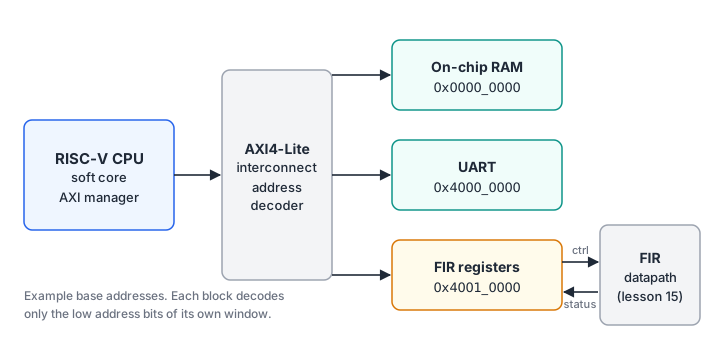
The interconnect decodes the high address bits to pick a subordinate, and each subordinate decodes only the low bits inside its window. In C, a register is a volatile pointer to a fixed address. volatile makes the compiler perform every read and write, in program order, instead of reusing a value it already loaded. A loop that polls a status bit through a plain pointer may never see the bit change.
On-chip buses
AXI4-Lite: five channels, one handshake
AXI is part of Arm’s AMBA family of on-chip buses. MicroBlaze V, the open cores above and the HLS kernels of the next lesson all offer AXI interfaces. AXI defines five independent channels:
| Channel | Direction | Carries |
|---|---|---|
| AW (write address) | manager → subordinate | AWADDR, AWPROT |
| W (write data) | manager → subordinate | WDATA, WSTRB (one byte-enable bit per byte) |
| B (write response) | subordinate → manager | BRESP |
| AR (read address) | manager → subordinate | ARADDR, ARPROT |
| R (read data) | subordinate → manager | RDATA, RRESP |
AXI4-Lite is the subset for control registers: every transaction is a single transfer, the data bus is 32 or 64 bits wide, and there are no bursts or exclusive accesses. The responses are OKAY (0b00), SLVERR (0b10) for an error reported by the subordinate, and DECERR (0b11), usually generated by the interconnect when no subordinate owns the address.
Every channel uses the same handshake. The source drives VALID when its information is ready, and the destination drives READY when it can accept. A transfer happens on a rising clock edge where both are high. The rules that matter for a correct design (IHI0022H.c, sections A3.2 and A3.3):
- A source must not wait for READY before asserting VALID.
- Once VALID is high, it stays high, with the information stable, until the transfer.
- A destination may wait for VALID before asserting READY. It may also assert READY first, and drop it again before VALID arrives.
- There is no ordering between AW and W. Data may arrive before the address, after it, or in the same cycle. In AXI4 the subordinate raises BVALID only after both the AW and the W handshakes.
- RVALID comes only after the AR handshake. The subordinate must not wait for RREADY or BREADY before raising RVALID or BVALID.
- There must be no combinational path from an input to an output of the interface.
During reset, ARESETn is low, the manager holds ARVALID, AWVALID and WVALID low, and the subordinate holds RVALID and BVALID low. Issue H.c is the last issue of the specification that describes AXI4-Lite; from Issue J on, the document covers AXI5 and AXI5-Lite instead.
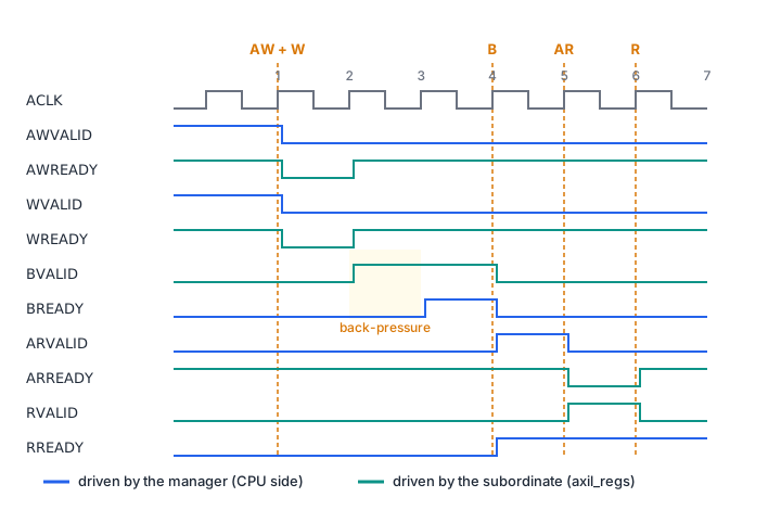
Avalon-MM in outline
Components in Altera’s Platform Designer, where Nios V systems are assembled, use the Avalon interfaces. Avalon-MM is an address-based read/write interface between a host and an agent, with one set of signals instead of five channels: address (a byte address by default), read, write, writedata, readdata and byteenable. An agent that cannot respond yet asserts waitrequest, and the host holds the transfer. For pipelined reads with variable latency, readdatavalid marks the cycles in which readdata is valid. A register file for one bus is easy to wrap for the other.
Worked example: a register file for the FIR filter
axil_regs.sv is an AXI4-Lite subordinate with this map:
| Offset | Name | Access | Meaning |
|---|---|---|---|
| 0x00 | CTRL | RW | bit 0 ENABLE (level); bit 1 START (write 1 for a one-cycle pulse, reads 0) |
| 0x04 | STATUS | RO | status_i from the hardware, for example BUSY (bit 0) and DONE (bit 1) |
| 0x08 | ID | RO | 0x46495231 (“FIR1”), so software can check that it found the right block |
| 0x0C | reserved | SLVERR | |
| 0x10 + 4k | COEF[k] | RW | coefficient k, k = 0 to N_COEF - 1 |
Addresses outside the map return SLVERR. Writes to read-only registers are ignored with OKAY, and WSTRB is honoured per byte. START is a write-one-to-pulse bit: software never has to clear it, and the hardware sees exactly one start pulse per write.
The write path holds AW and W in two one-entry registers. Each channel’s READY is low only while its holding register is full, so the two channels are accepted independently:
assign s_axil_awready = !aw_full;
assign s_axil_wready  = !w_full;
assign do_write = aw_full && w_full && !s_axil_bvalid;

always_ff @(posedge aclk) begin
    start_o <= 1'b0;                          // default: no pulse
    if (!aresetn) begin
        aw_full <= 1'b0;  w_full <= 1'b0;  s_axil_bvalid <= 1'b0;  // ...
    end else begin
        if (aw_hs) begin aw_full <= 1'b1; aw_word <= s_axil_awaddr[ADDR_W-1:2]; end
        if (w_hs)  begin w_full  <= 1'b1; w_data <= s_axil_wdata; w_strb <= s_axil_wstrb; end
        if (do_write) begin
            aw_full <= 1'b0;  w_full <= 1'b0;
            s_axil_bvalid <= 1'b1;
            s_axil_bresp  <= mapped(aw_word) ? OKAY : SLVERR;
            // ... update CTRL or COEF[k] using w_strb
        end else if (s_axil_bvalid && s_axil_bready) begin
            s_axil_bvalid <= 1'b0;
        end
    end
end
do_write waits for both halves and for the previous response to be accepted (rules 4 and 5). A full holding register keeps its READY low, so a new address cannot overwrite one still waiting for its data. The read path allows one read in flight: ARREADY is !rvalid. All READY and VALID outputs come from registers (rule 6), at the cost of at most one read every two cycles.
axil_regs.sv
Verifying the bus interface
Bus bugs hide until a manager uses a timing your tests never produced, so the tests vary the timing on purpose.
tb_axil_regs.sv is a self-checking SystemVerilog testbench. Its axi_write task drives AW and W from separate fork threads, so a write can present them together, address first or data first. It also holds BREADY and RREADY low for several cycles, checks byte strobes, the START pulse, STATUS and SLVERR, and prints PASS: 42 checks.
cocotb_axil_regs.py is a Python AXI4-Lite manager. Each channel driver raises VALID after a random delay and holds it until READY. A background coroutine toggles BREADY and RREADY at random, and a monitor checks on every cycle that BVALID and RVALID never drop or change before their handshake, and that no response comes before its request. One test runs 600 random transactions against a Python model of the register map. Another streams writes on AW and W without waiting for responses; it catches a subordinate that keeps AWREADY high while an address is still held, because the second address then overwrites the first. The tests read the register offsets from the C header, so RTL and software cannot drift apart.
tb_axil_regs.sv
Download cocotb_axil_regs.py
Download test_cocotb_axil_regs.py
Download sim_runner.py
The software side
fir_regs.h holds the offsets and bit masks and wraps each access in a function that takes a fir_dev with the base pointer. fir_drv.c checks the ID, writes sign-extended Q1.15 coefficients, starts the block and polls STATUS with a limit:
fir_dev dev;
if (fir_init(&dev, (volatile uint32_t *)0x40010000u) != 0) { /* wrong block */ }
fir_set_coefs(&dev, coef_q15, 8);
fir_start(&dev);
if (fir_wait_done(&dev, 100000) < 0) { /* timeout */ }
The driver only knows a base pointer, so you can test it on your PC. test_fir_drv.c points it at an ordinary uint32_t array and checks what lands there: -39 becomes 0xFFFFFFD9, too many coefficients are rejected before any write, and polling times out while BUSY is set. Build it with clang -std=c11 -Wall -Wextra -Werror fir_drv.c test_fir_drv.c; it prints PASS and returns 0. test_fir_drv.py runs the same build from pytest.
fir_regs.h
Download fir_drv.c
Download test_fir_drv.c
Add a sample counter register
Add a read-only register COUNT at offset 0x0C (the reserved word), fed by a new input count_i that counts samples since the last START. What changes in axil_regs.sv, fir_regs.h and the tests, and which test fails if you update the header but forget the RTL?
Show solution
In axil_regs.sv: add input logic [31:0] count_i, a localparam A_COUNT = 3, a case item A_COUNT: rd_mux = count_i;, and add w == A_COUNT to mapped(). Writes to it then return OKAY and are ignored, like STATUS.
In fir_regs.h: #define FIR_REG_COUNT 0x0Cu.
In cocotb_axil_regs.py: read A_COUNT from the header, add it to RegModel.mapped(), return the driven value from RegModel.read(), and drive count_i in setup(). The random test already accesses 0x0C, so it now expects OKAY instead of SLVERR.
In tb_axil_regs.sv: test 6 expects SLVERR at 0x0C. Change it to expect OKAY and the value you drive on count_i.
If only the header and model change, random_traffic_with_backpressure fails at the first access to 0x0C, because the RTL still answers SLVERR.
Summary
- Put pipelines in hardware and control in software. A processor handles sequencing, protocols and settings that change, through a small set of registers.
- Hard cores (PolarFire SoC: RV64IMAC monitor core plus four RV64GC cores) are fast and fixed. Soft cores (Nios V, MicroBlaze V, PicoRV32, VexRiscv, NEORV32) cost fabric and are configurable.
- RISC-V names list a base ISA and extensions: RV32I, plus M (multiply/divide), A, F, D, C (compressed); G is IMAFDZicsr_Zifencei.
- AXI4-Lite has five channels with one VALID/READY rule set: VALID never waits for READY and stays high until the transfer, AW and W are unordered, BVALID follows both handshakes, and no input drives an output combinationally.
- A register file is the hardware/software contract. Verify it with random back-pressure and reordered channels, keep the offsets in one header, and test the C driver on the host against a mocked array.
Check your understanding
Pick an answer for each question, then check. Answers stay hidden until you submit.
Further reading
- Standard
- Standard
- Documentation
- Documentation
- Documentation
- Tool
Found a mistake or something unclear?Report a correction.
Follow this course
Get an email when new lessons and projects are added to this course.